This is an old revision of the document!
Locator receiver variants
There are several known variants of the Datatrak receiver, all of which are known as Locators.
Mk.I
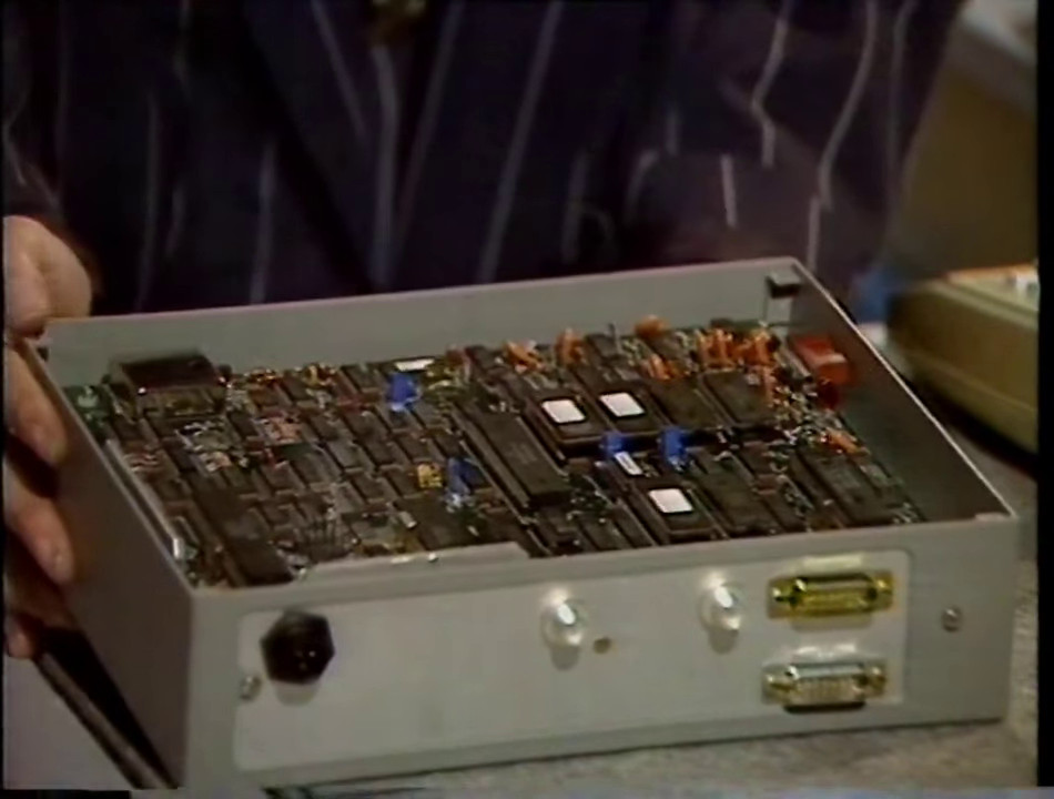
The Mk.1 was the original Locator. It was a fairly large box consisting of several PCBs, mostly loaded with TTL parts which implemented the function of the ASIC.
I have yet to see a Mk.1 Locator “in the wild”.
The Locator shown on BBC Tomorrow's World in 1987 is believed to be a Mk1 or prototype Locator.
Mk.II series (including Mk.IId and Mk.II TrakBak)

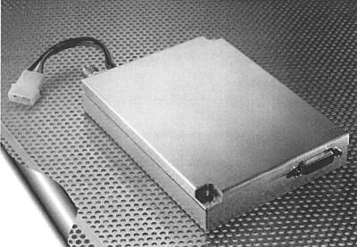
These units were available in black and silver, but black seems to be the most common.
There were at least two variants available:
- Nav-only receivers don't include an EPROM for the 8032 secondary processor, and usually entirely omit the UHF transmitter and PA board.
- Trakbak receivers include the EPROM and UHF transmitter, and replace the “Datatrak” cover on the software ROM slot with a plain one.
Physical construction
The Mk.II is built into a fairly heavy extruded aluminium box.
Four screws secure the front panel, with the same on the rear. There are two PCBs internal to the unit – a UHF power amplifier on the top of the metal shield plate, and the processor and LF receiver on the base board.
The UHF PA may not be present in some units. These units will typically be navigation-only and have no Radio EPROM. There is a “costdown” variant of the main PCB which omits the 8032 secondary processor, ROM, RAM and support components.
Power supply section
The Mk.II accepts power through a 3-pin XLR connector. This carries the 13.8V vehicle DC supply voltage, ground and an ignition sense wire. Turning on the ignition powers on the receiver. Normally a loss of ignition sense will cause the receiver to shut down.
The XLR pinout is shown on the page Mk.II Locator pinouts.
LF receiver section
The receiver section is broadly similar to the phase-measuring Decca receiver described in (Last et al, 1984).
The Datatrak LF signal is received by an amplified dual-band antenna. This antenna (described in the patents EP0608992 and GB2274548B) serves as a receive/transmit antenna for the UHF band and a bandwidth-limited active receive antenna for the LF signal.
The receiver provides an 8V DC bias supply to the TNC antenna connector to supply power an active antenna amplifier.
The local oscillator signal is generated by mixing two signals with an SA602:
- A fixed $\frac{20\mathrm{MHz}}{200} = 100 \mathrm{kHz}$ signal.
- A switchable $\frac{20\mathrm{MHz}}{756} = 26.455 \mathrm{kHz}$ or $\frac{20\mathrm{MHz}}{1512} = 13.2275 \mathrm{kHz}$ signal.
The resulting signal is filtered to remove the low-side mixing product ($100\mathrm{kHz} - F$), leaving the high-side mixing product ($100\mathrm{kHz} + F$).
The received LF signal is mixed with the local oscillator by an SA605 FM receiver IC to create a 20kHz intermediate frequency. This is then processed by the IF filter, which has a bandwidth of around 200Hz.
The filtered IF is fed to the SA605's limiting amplifier, which removes the effect of fading from the received signal. The resulting square wave is cleaned up with an LM393 comparator to produce the digital signal for the ASIC.
The ASIC measures the phase of the 20kHz IF using the 20MHz TCXO-derived reference. This gives a phase measurement resolution of 1 in 1000 (one-thousandth of an IF cycle). The Datatrak documents refer to these as millicycles.
Mk.III
I have no data on the Mk.III, and have yet to see one “in the wild”.
Mk.IV
The Mk.IV (Mark 4) Locator was a significant improvement on previous Locator designs.
- CPU: The 68000 processor was replaced with a Motorola 68340 “CPU32” embedded processor.
- ASIC: Newer version of the ASIC which operates on 20-bit sampled analog I/Q data from the RF front end.
I have yet to see one of these receivers “in the wild”.