HackTV
HackTV is a software package which turns the HackRF One into an analog TV transmitter.
There are two versions of HackTV:
- fsphil's main repo – the “official” HackTV
- Captain Jack's fork – which adds support for several video encryption and CA systems, e.g. Videocrypt and Eurocrypt.
I've put together some pages about the work I've done with HackTV:
- The Videocrypt PPV Token System – (TODO) – A description of the never-deployed Videocrypt token PPV system, based on Phonecard-style smartcards
- BSB DMAC receivers including the Trac Satellite modification to the Ferguson SRB1.
HackTV Quick Start
PAL terrestrial
./hacktv -f 855250000 -g 36 -s 14000000 -m i --filter VIDEOFILE
- -f: Modulation centre frequency. 855.25 MHz is UHF channel 69.
- Alternatively 471.25MHz is Channel 21.
- -g: Transmit LNA gain.
- -s: Sample rate. A multiple of 14 MHz is required for VideoCrypt.
- -m: Mode. VSB-modulated PAL System-I
- --filter: Enable VSB modulation filter. Improves video quality, but VSB-AM usually looks good without it.
For other channel/frequency mappings, refer to the frequency list on Wikipedia.
BBC Select
At least for the BBC Selector decoder box I borrowed, the channel assignments are:
- Programme 1 and 3: C46 = 671.25 MHz
- Programme 2 and 4: C40 = 623.25 MHz
- Selector video out: C35 = 583.25 MHz
PAL satellite
./hacktv -f 1093e6 -D 10000000 -g 36 -s 14000000 -m pal-fm --filter VIDEOFILE
- -f: Modulation centre frequency. With “FSS LNB” (10 GHz LO), this would be a tuning frequency of 11378 (MHz).
- -D: Deviation.
- This is total deviation (twice the ± deviation).
- ASTRA used 16 MHz/V deviation in a 26 MHz bandwidth channel, with 0.7V between white and black levels. This implies a 0.3V sync level, giving a 1V peak-to-peak video signal with 16 MHz total deviation (± 8 MHz). This is given in "Baseband parameters for FM TV transmission" (archive link)
- The practical minimum for an ASTRA receiver and VideoCrypt decoder to work is around 9 MHz total deviation (± 4.5 MHz).
- The HackRF is limited to 20 MHz bandwidth.
- To go higher, a LimeSDR or similar high-bandwidth SDR transmitter is required.
- Using Carson's rule: Peak freq deviation = (RF bandwidth - 2 (maximum video freq) ) / 2 MHz
- ASTRA: $\left( 26 - \left(2 \times 5 \right) \right) \div 2 = \left( 26 - 10 \right) \div 2 = 8 \, \mathrm{MHz}$. This is HackTV's default.
- HackRF maximum: $\left( 20 - \left(2 \times 5 \right) \right) \div 2 = \left( 20 - 10 \right) \div 2 = 5 \, \mathrm{MHz}$. This is a HackTV deviation parameter of
-D 10000000.
- -g: Transmit LNA gain. 47dB in this example.
- -s: Sample rate. A multiple of 14 MHz is required for VideoCrypt.
- -m: Mode. FM-modulated PAL.
- –filter: Enable PAL pre-emphasis filter. Requires de-emphasis to be enabled in the receiver or decoder.
- On the SVA1, this is done by setting the “De-emphasis” switch to “In”.
BSB DMAC
./hacktv -f 1092.56e6 -g 36 -s 20250000 -m dmac-fm --filter VIDEOFILE
1092.56 MHz is Galaxy, Channel ID 0x70B2. Other options on a BSB receiver are:
| Channel No. | Transponder | RF frequency (MHz) | IF frequency (MHz) | Channel ID (CHID) | Channel name |
|---|---|---|---|---|---|
| 1 | 20 | 12091.90 | 1322.72 | E8B5 | The Movie Channel |
| 2 | 12 | 11938.46 | 1169.28 | 48B3 | The Sports Channel / The Computer Channel |
| 3 | 8 | 11861.74 | 1092.56 | 70B2 | Galaxy |
| 4 | 16 | 12015.18 | 1246.00 | D0B4 | The Power Station |
| 5 | 4 | 11785.02 | 1015.84 | 20B1 | Now |
| 6 | 2 | 977.48 | |||
| 7 | 6 | 1054.20 | |||
| 8 | 10 | 1130.92 | |||
| 9 | 14 | 1207.64 | |||
| 10 | 18 | 1284.36 |
The IF frequency can be obtained from the transponder number with the following formula:
$F_{IF} = ({Transponder} \times 19.18) + 939.12 \, \mathrm{(MHz)}$
The satellite frequency can be obtained from the IF frequency:
$F_{SAT} = F_{IF} + 10769.18 \, \mathrm{(MHz)}$
To set the Channel ID, use the --chid command line parameter, e.g.: --chid 0xB4 for Power Station.
D2-MAC
./hacktv -f 1378.56e6 -g 47 -s 20250000 -m d2mac-fm --eurocrypt tv1000 --filter VIDEOFILE
Use with LimeSDR
Include -o soapysdr:lime in the HackTV command line.
I can't recommend the LimeSDR, the hardware is horribly unreliable. Mine failed irreparably after only a few hours of use. The warranty being only 30 days should tell you everything you need to know!
Connecting video to an SVA1 Videocrypt decoder
The ASTRA “Decoder” port is pinned as follows:
| Looking into the rear panel of the decoder | Looking into the plug |
|---|---|
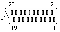 | 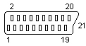 |
| 21-pin SCART female (socket) | 21-pin SCART male (plug) |
| Pin | Function | Notes |
|---|---|---|
| 1 | Audio Right | |
| 2 | Audio Right | |
| 3 | Audio Left | |
| 4 | Audio Ground | |
| 5 | (Pace) RGB Blue ground | |
| 6 | Audio Left | |
| 7 | (Pace) RGB Blue signal | |
| 8 | Ext Dec Status | 0V = decoder inactive 9-12V = decoder active |
| 9 | (Pace) RGB Green ground | |
| 10 | (Pace) Ext Switch (Amstrad) PAL baseband out (unfiltered and unclamped) | Not connected on Pace SS9000 Relay Drive output on Pace MSS200/MSS300/Apollo |
| 11 | (Pace) RGB Green signal | |
| 12 | (Pace) Serial Data I/O (Amstrad) MAC baseband out | Pace - used to communicate with a Pace dish positioner |
| 13 | (Pace) RGB Red ground | |
| 14 | Fast blanking ground | |
| 15 | (Pace) RGB Red signal | |
| 16 | (Pace) RGB status in | aka Fast Blanking in |
| 17 | Video Out ground | |
| 18 | Video In ground | |
| 19 | PAL Baseband video out (filtered and clamped) | |
| 20 | Video In | |
| 21 | Ground/shield (SCART case) |
The decoder connects to the satellite receiver using an ordinary SCART cable, which connects the “in” pins on one side to the “out” pins of the other (and vice versa).
To feed video into an SVA1, make the following connections:
- Supply video to the decoder on pin 20 (with ground on pin 18)
- Take video out of the decoder from pin 19 (with ground on pin 17)