ST-Link/V2 (or clone) to Black Magic conversion
The hobby electronics market has been flooded with clones of the ST ST-Link/V2 programmer. While the original isn't expensive, it does have some limitations which can be annoying:
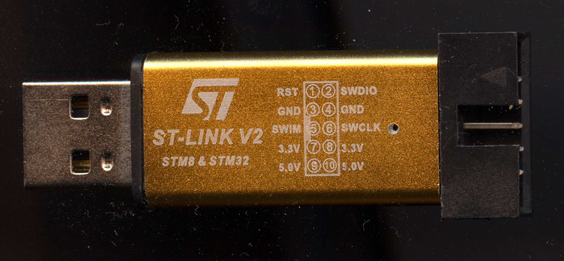
- The ST-Link/V2 uses the industry-standard JTAG and SWD protocols, but only works with ST parts.
- The standalone ST-Link doesn't include the UART port which is present on the development boards.
Installing the Black Magic Probe firmware on the ST-Link removes these limitations, and converts the ST-Link/V2 into a generic 3.3V JTAG and SWD adapter, which can be used to program and debug a variety of ARM Cortex microcontrollers (using SWD), or program other parts like FPGAs and CPLDs which use the industry-standard JTAG interface.
 Warning: Warning: |
|---|
| Newer models of the cloned ST-Link/V2 have appeared, which don't use the STM32F103CB processor. Instead, an STM32F101 part (which has no USB interface), an STM32F103C8 (which has only 64K of Flash) or a clone of one of these will be fitted. To use these boards, the processor chip may need to be replaced with a genuine STM32F103CB in the appropriate package. |
Instructions
Note: The current versions of the Black Magic Probe firmware are too large to fit in the ST-Link's Flash. There's an issue open for this on the BMP Github page with some suggestions. I've found that version 1.9.3 is the last version which will fit in Flash as a complete build.
For more recent versions, you will need to remove one or more targets from the SRC += block in src/Makefile and rebuild.
Downloading and building the Black Magic firmware
# Install build prerequisites:
#   * The GCC cross-compiler for embedded ARM
$ sudo apt install gcc-arm-none-eabi

# Clone the Black Magic source code and check out the latest tag
$ git clone https://github.com/blackmagic-debug/blackmagic.git
$ git checkout `git describe --tags --abbrev=0`

# Build the firmware
make clean
make PROBE_HOST=stlink
Installing the Black Magic bootloader
- Disassemble the ST-Link by removing the cap, and pushing the USB connector down on a hard surface while holding the aluminium case. The PCB should slide out of the other end.
- Remove the PCB from the case
- Connect another ST-Link to the programming pads on the PCB – you will need to identify these by tracing them back to the CPU power and programming pins.
- Follow the instructions below to reprogram the chip:
- ST-Link/V2 with ST firmware, using the st-flash utility:
openocd -f interface/stlink-v2.cfg -f target/stm32f1x_stlink.cfg -c "init" -c "halt" -c "stm32f1x unlock 0" -c "shutdown"
st-flash erase
st-flash --reset write blackmagic.bin 0x8002000
st-flash write blackmagic_dfu.bin 0x8000000
- Using another Black Magic Probe (from https://wiki.paparazziuav.org/wiki/STLink)
(gdb) target extended-remote /dev/ttyACM0
(gdb) mon swdp_scan
(gdb) att 1
(gdb) mon option erase
(gdb) load /dir/to/blackmagic
(gdb) load /dir/to/blackmagic_dfu
(gdb) detach
- Using OpenOCD
Installing or upgrading the firmware
# Install Rust
$ sudo apt install cargo

# Clone and build the Black Magic Probe utility
$ git clone https://github.com/blackmagic-debug/bmputil.git
$ ( cd bmputil; cargo install --path . )

# Identify Black Magic Probe (optional)
$ sudo ~/.cargo/bin/bmputil info
Found: Black Magic Probe (STLINK), (Firmware v1.6.1-319-ge52e2f5)
  Serial: (redacted)
  Port:  1-4

# Flash the firmware
$ sudo ~/.cargo/bin/bmputil flash ./blackmagic/src/blackmagic.elf
Found: Black Magic Probe (STLINK), (Firmware v1.6.1-319-ge52e2f5)
  Serial: (redacted)
  Port:  1-4
Erasing flash...
Flashing...
 100% |██████████████████████████████████████████████████| 110.10KiB/110.10KiB [4.65KiB/s 23s]
Black Magic Probe successfully rebooted into firmware version (ST-Link/v2) v1.9.0-rc1
Serial port and SWO Trace modification
The Black Magic Probe firmware adds UART and SWO trace support to the ST-Link. These features are not normally available on the cloned ST-Links, but using them requires some hardware modifications. To do this, you will need a steady hand.
Thankfully the Mini ST-Link doubles-up some of the power supply pins on the 10-pin connector. We can disconnect these and re-use them for TRACESWO and UART support.
The connector pinout will change to:
| New function | Old function | Wire connects to |
|---|---|---|
UART TX | 5V | STM32 PA2 (pin 12) |
UART RX | 3V3 | STM32 PA3 (pin 13) |
TRACESWO | GND | STM32 PA10 (pin 31) |
There are two methods I've used to make this modification:
- Kapton Tape method
- Track cut method
Kapton tape method
This method works on all Mini ST-Link PCB layouts, but can be quite fiddly, and reduces the mechanical strength of the connector.
- Desolder the side of the 10-pin connector which is on the same side as the STM32F103RB processor.
- This should be the side with the SWIM pin on it.
- Slide Kapton or similar insulating tape under the pins.
- Check with a multimeter to make sure the pins don't connect to the PCB traces.
- Install wires as per the table above.
- Use thin magnet wire, e.g. Roadrunner wire.
- Resolder the RST and SWIM pins to the PCB.
- Test your work:
- Visual check – is the soldering sound? are there any short circuits?.
- Electrical check – use a multimeter or continuity tester to check continuity.
- Loopback test – connect RX to TX on the serial port and check data is looped back.
- Tack down the wires with a small amount of glue.

Track cut method
This method gives a more mechanically-sound result, but only suitable for boards where the track layout allows the pins to be cleanly disconnected. The blue-PCB probe I had couldn't be modified like this, as the 5V and 3V3 pads had vias which connected power from one side of the PCB to the other. The track layout gave away that these vias were there: there was no other way 5V and 3V3 could connect from one side of the board to the other.
The green “Mini ST-Link V2 E” PCB had vias next to the pads, which could be disconnected from the pads with no ill effect.
- Cut the tracks leading to the
5V,3V3andSWIMpins on the 10-pin connector.- These should be on the same side as the STM32F103CB CPU.
- Install wires as per the table above
- Test your work:
- Visual check – is the soldering sound? are there any short circuits?.
- Electrical check – use a multimeter or continuity tester to check continuity.
- Loopback test – connect RX to TX on the serial port and check data is looped back.
- Tack down the wires with a small amount of glue.

External links
- Clone ST-Link/V2 repurposing: shows a way of connecting to the programming pads with test clips.