Converting a Gorgy LEDI-6/S studio clock to WiFi+NTP
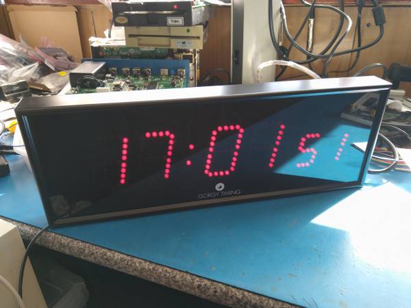
I picked up a Gorgy Timing LEDI-6/S studio clock at the 2021 Peaker Pattinson S4C auction. This page explains how I got it to do something useful…
These clocks take
The easy way out... (manually setting the clock)
The first thing I did was try to dig up some documentation – Gorgy Timing's support team were kind enough to send me the user guide, and a deeper search of the Internet turned up the LEDI-6 SMPTE Timecode Option manual.
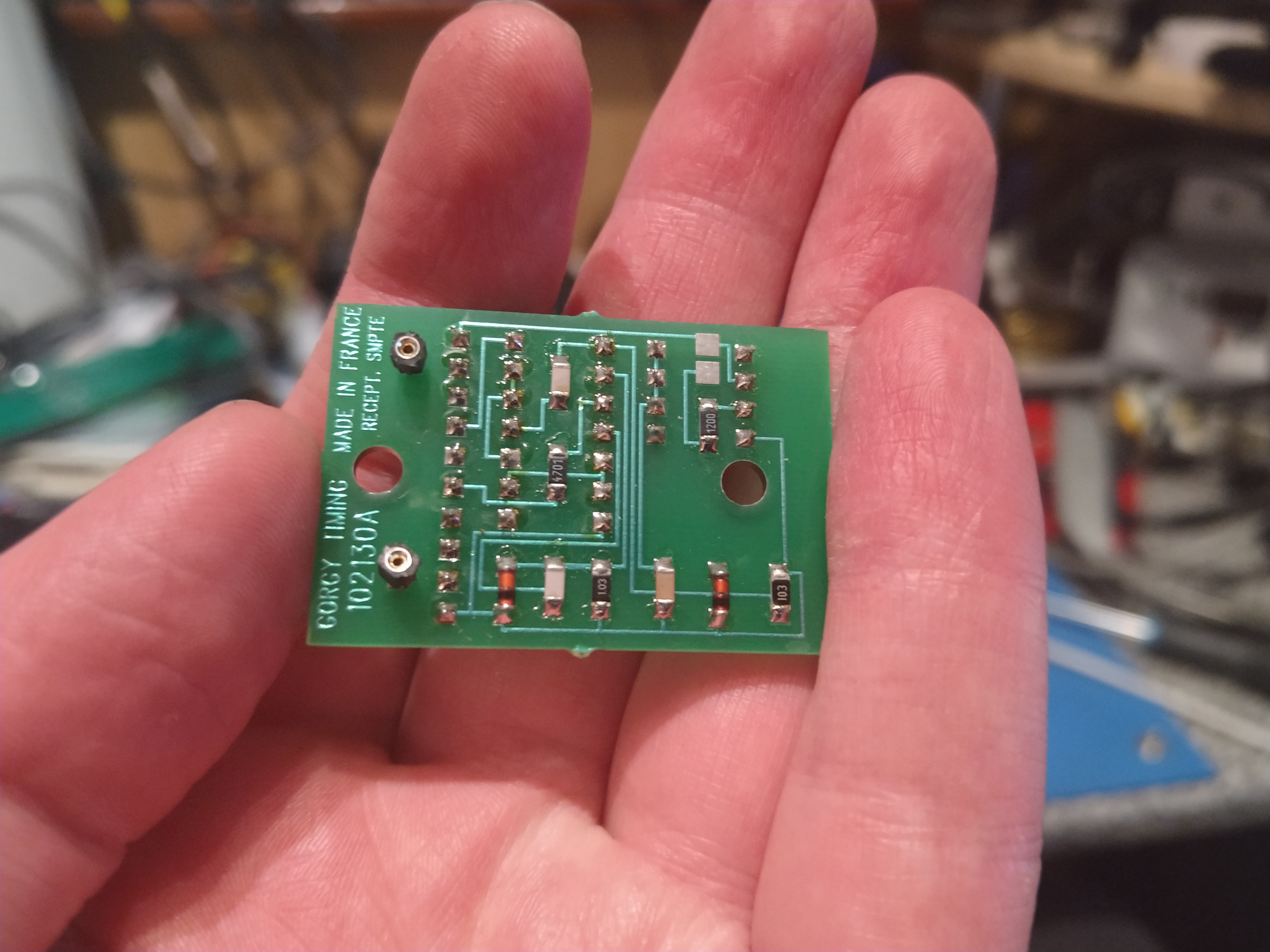
I also found an old Gorgy product catalogue which shows how to identify the clock from the Code number on the back label. I have a 3667/110S0 – which turns out to be a wall-mount LEDI-6/S with seconds display, SMPTE timecodes and a red display. This was easily confirmed by removing the back to reveal a set of PCBs labelled “LEDI 6/6S”, and a tiny plug-in PCB labelled “SMPTE”.
The user guide suggests that the time can be set using the “PROG” (labelled “C”) button on the rear panel – but this is not true for the SMPTE Timecode variant. The timecode receiver clocks don't allow the clock to be manually set, and require an incoming SMPTE-format timecode. The date and time are captured from the stream and used to set the clock. Sadly this removes the easy way out (manually setting the clock)… I need to create a timecode.
A stich in time - replacing the battery
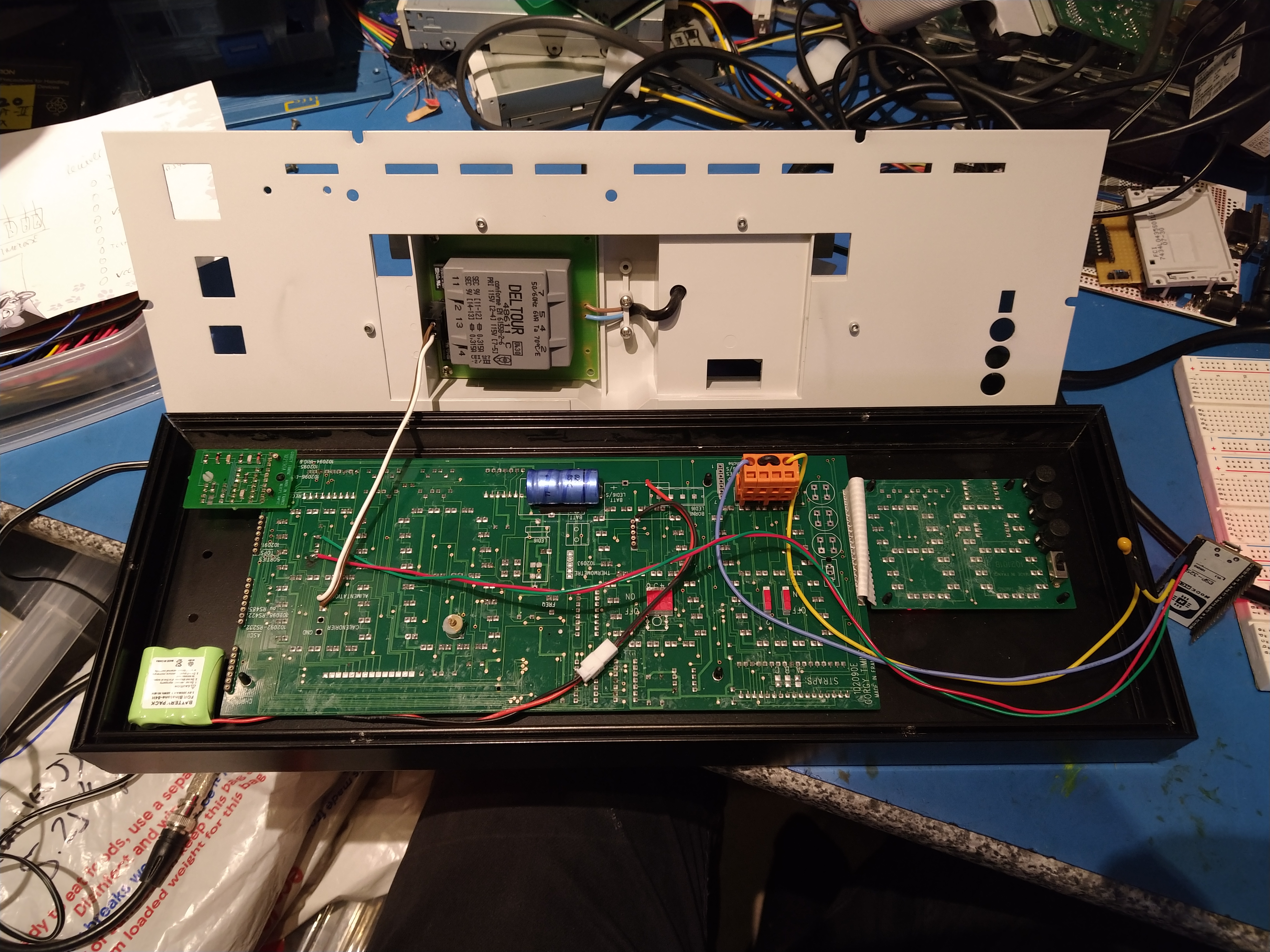
The first thing I noticed with the back cover removed was a 3.6V Varta Mempac battery, merrily leaking away onto the PCB. This was quickly desoldered and replaced with a short length of wire leading to an off-board 3.6V 300mAh cordless phone battery. Now if the battery leaks in future, I should have a fair while before it risks damaging the PCBs.
As the battery had already leaked, I dabbed on a small amount of distilled vinegar to neutralise the battery electrolyte, and washed off the residue with 60% isopropyl. Thankfully there was no PCB damage to repair.
Connecting a timecode
First, the important part – the pinout of the timecode connector:
| Pin | 1 | 2 | 3 | 4 |
|---|---|---|---|---|
| Function | TC A | Linked | TC B | |
The timecode signal is connected to pins 1 and 4 (the two outside pins) of the timecode connector. The inside two pins are linked.
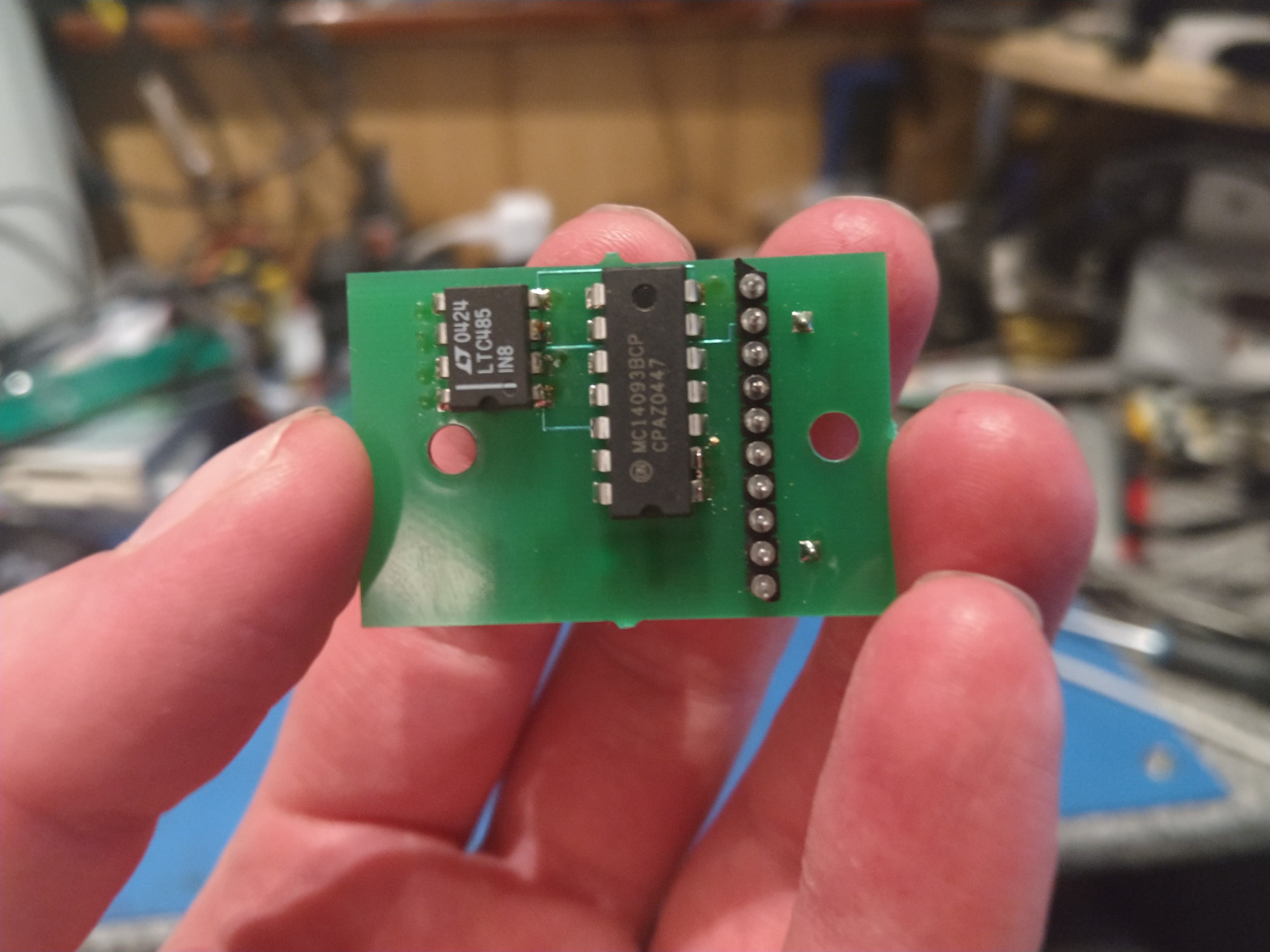
While I was inside the clock, I looked at the timecode interface PCB. The small PCB hosts an LTC485 RS485 receiver IC, and a 4093 CMOS gate. The LSTTL gate is wired to produce a 10us pulse every time there's an edge on the timecode signal.
The RS485 receiver's 'A' input is connected to pin 4 of the timecode connector, and conversely its 'B' input is connected to pin 1. There is no ground connection between the timecode generator and the clock. As there is no common ground, the timecode signal must be AC coupled. That is to say, the clock will not detect a DC-coupled timecode.
Timecode receiver board
I've partially reverse-engineered the timecode receiver board's 10-pin Harwin-style turned-pin connector:
| Pin | Function |
|---|---|
| 1 | Timecode In - connects to pin 1 of the input connector. |
| 2 | Timecode In - connects to pin 4 of the input connector. |
| 3 | (3.3V?) |
| 4 | (AC coupled LTC?) |
| 5 | +12V |
| 6 | Edge detected timecode - 10.5us positive pulse for every L→H or H→L edge of the timecode input. |
| 7 | Timecode Presence In - connects to pin 2 of the input connector. |
| 8 | |
| 9 | |
| 10 | +5V |
Photos of the PCB are shown below. These can be clicked to enlarge them:
Bring forth the SMPTE!
I spent a while digging and found a few useful references on the SMPTE timecode format:
- A Wikipedia page on linear timecodes (including the SMPTE/EBU timecode)
- The formal specification for the SMPTE timecode: ITU-R Recommendation BR.780-2
- The EBU's extensions to the SMPTE timecode: EBU Tech 3097
The clock is extremely picky about timecode formats and accuracy. My attempts to generate timecodes using delay-loops and port-writes on an Arduino resulted in failure. I expect that something based on timer interrupts may work much better – but this was only intended as a stepping stone.
After further searching, I found that Dirk-Willem van Gulik had developed an open-source ESP32-based timecode generator which creatively uses the ESP32's IR transmitter module to generate SMPTE timecodes. The ESP32's WiFi port is put to good use: the ESP connects to a WiFi network, then connects to an NTP server to retrieve the current time. There's no network timing compensation so the accuracy is (at best) around a few hundred milliseconds, but this is good enough for a wall clock.
I made a few small changes to the code to set it up for my WiFi network, 25FPS output, and to use the 0.pool.ntp.org NTP server as provided by ntp.org.
Installing an ESP32 in the clock
This turned out to be pretty simple:
- Desolder the pins from the ESP32 board (or use a pinless ESP32 board). I used a NodeMCU style ESP32 board.
- Fit a 6-pin header in the bottom corner of the ESP32's pin stack, where the 5V pin is located.
- Program the ESP32 with the code, using the Arduino IDE and ESP32 tools.
- Solder two wires to the pins of the 5V voltage regulator (on the LEDI motherboard) to grab 5V power for the ESP32 – connect these to
5Vand0Von the ESP32 board using a plug-in connector. - Tin the ends of two wires and install them into the timecode input connector. Plug this into the motherboard, and lead the wires to a convenient location for the ESP32 board.
- Connect one of the two wires to 0V on the ESP32.
- Connect the other wire to GPIO 12 on the ESP32, via a 10uF electrolytic capacitor. The positive end should connect to the ESP32.
This photo shows the position of the 5V wiring and the battery. Click to enlarge it.

Now you should be able to power on the clock, and the clock should appear. After a few seconds the ESP should connect to the WiFi, retrieve the current date and time, and display it. A flashing colon indicates that the timecode is valid – a static colon (always-on or always-off) indicates that the clock is not receiving a valid timecode.
Some ESP32s are a bit power hungry and make the LEDs on the clock flicker. You could try connecting a capacitor over the 5V regulator or the ESP32 pins, or try a different module (e.g. one using the ESP32D-WROOM-32D chip). I had this problem with an AZ-Delivery module, and switched to a different module.
I've also had issues with the AZ-Delivery module failing to reset when fitted to the clock – if your module does this, you could try one of the following tricks:
- Connecting a 10uF capacitor between the EN pin (positive pin) and ground (negative pin)
- Connecting a pull-up resistor (around 10k) between the IO0 pin and 3.3V
If you continue to have issues… try a different ESP32 module.
The ESP32 can be fitted above the seconds display – there's a huge area of empty space which can be seen in the following photo:
Wall mount
My clock didn't come with a wall mount, so I designed one based on the dimensions in the manual.
STL and OpenSCAD files for the LEDI-6 wall bracket
This prints easily in PETG or PLA, but will require a large print bed.